Method for analysing the wind stability of tower cranes: OptiFluides simulation software

OptiFluides develops software to validate the safety of cranes exposed to wind in urban environments.

Logiciel CFD d'étude de la sécurité des grues au vent

Why study the safety of cranes exposed to wind?

Tower cranes play a key role on construction sites, particularly in the construction of high-rise buildings. These machines can support loads of up to several tonnes (often between 20 and 80 tonnes depending on the model) and can move these loads to heights of over 80 metres, or even much higher depending on the needs of the site.

However, their use requires extreme vigilance: the most frequent incidents result from falling loads, collisions between cranes, accidents during work at height, or even wind-related overturns. It is this last risk that we are studying here.

Site effects: a source of incidents

On urban construction sites, the stability of tower cranes is crucial, even when they are not in use.

When the crane is out of service, it is placed in weathervane position. Generally speaking, for a given wind speed, the crane is positioned to minimize the force exerted by the wind, i.e., the crane jib is oriented in the direction of the wind (it is positioned downwind). This is the normal weathervane position. However, on a construction site, the wind profile in the area in question may be modified locally by the presence of buildings: this is known as site effects. The aerodynamic behavior of the rotating part of the crane, consisting of the jib and counter jib, is significantly affected by this.

The position of the crane may differ from that of the normal weathervane, and the aerodynamic forces exerted by the wind on the crane may also be increased. The effects of wind, modified locally by buildings, can cause:

  • Misalignment of the crane with respect to the direction of the wind in a flat field: departure from the weathervane position;
  • The crane jib to go into self-rotation;
  • Unforeseen mechanical overloads, or even material damage;
  • Increased safety risks, up to and including the crane tipping over.

We have developed a method for analyzing the effects of wind on crane stability based on CFD simulation and dynamic crane modeling.

Our CFD software solution by Optifluides

  • Numerical simulation of airflow at site level using the OpenFOAM® code;
  • Modeling of crane jib dynamics using an internally developed tool;
  • Multi-scenario analysis: 36 wind directions × 36 initial crane jib orientations;
  • Automated calculation of stability coefficients;

CFD simulation of crane wind resistance in 4 steps

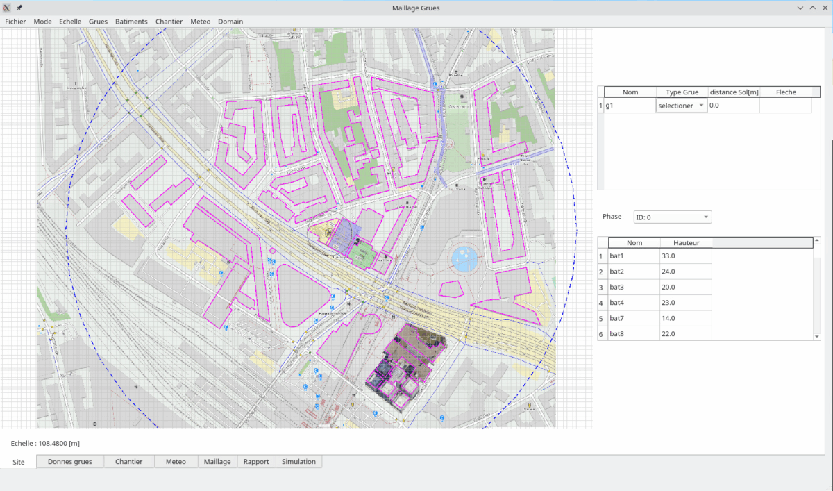
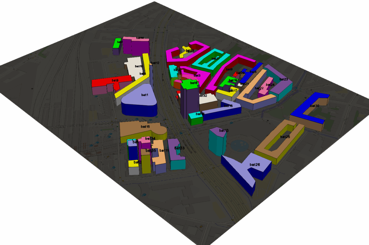
  • 1st step: automated reconstruction of the 3D model of the site within a radius of 400 to 900 m around the crane
Présentation de l'outil logiciel pour l'étude de stabilité des grues au vent Présentation du rendu de mise en donnée avec l'outil logiciel pour l'étude de stabilité des grues au vent
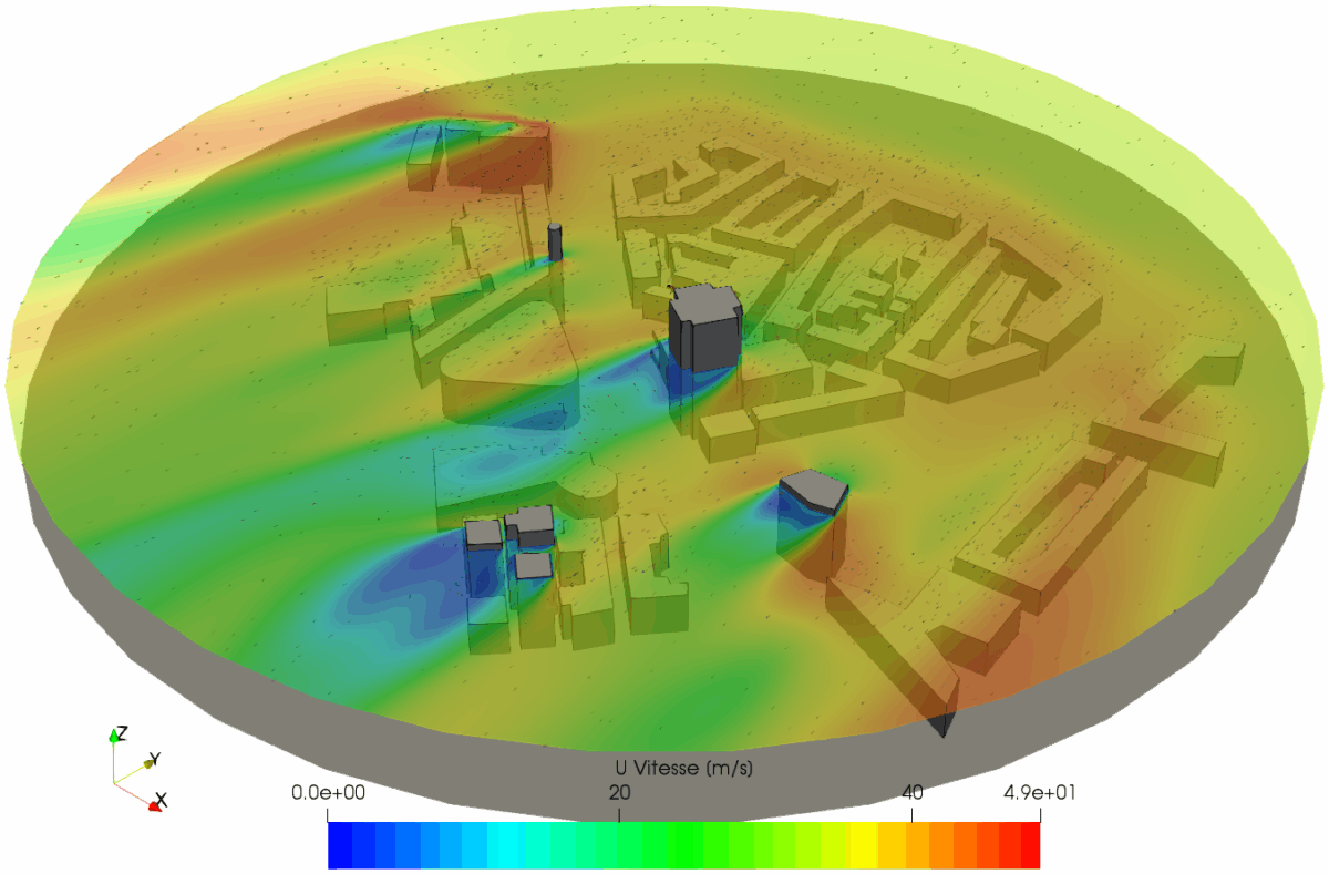
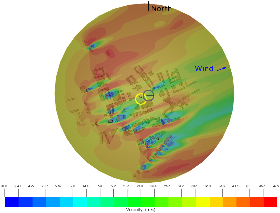
  • 2nd step: wind simulation for 36 directions (from 0° to 360° in 10° increments)

Exemple de résultats : champ de vitesse de vent pour une direction donnée

  • 3rd step: integration of the crane into the wind field to calculate the movement of the crane jib and deduce the forces it is subjected to

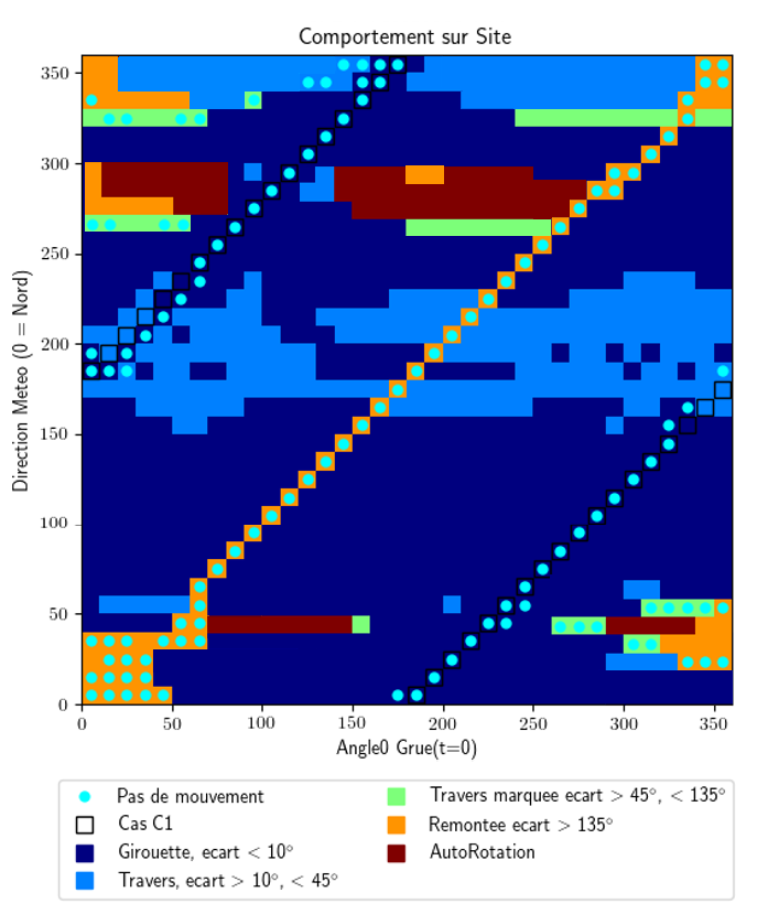
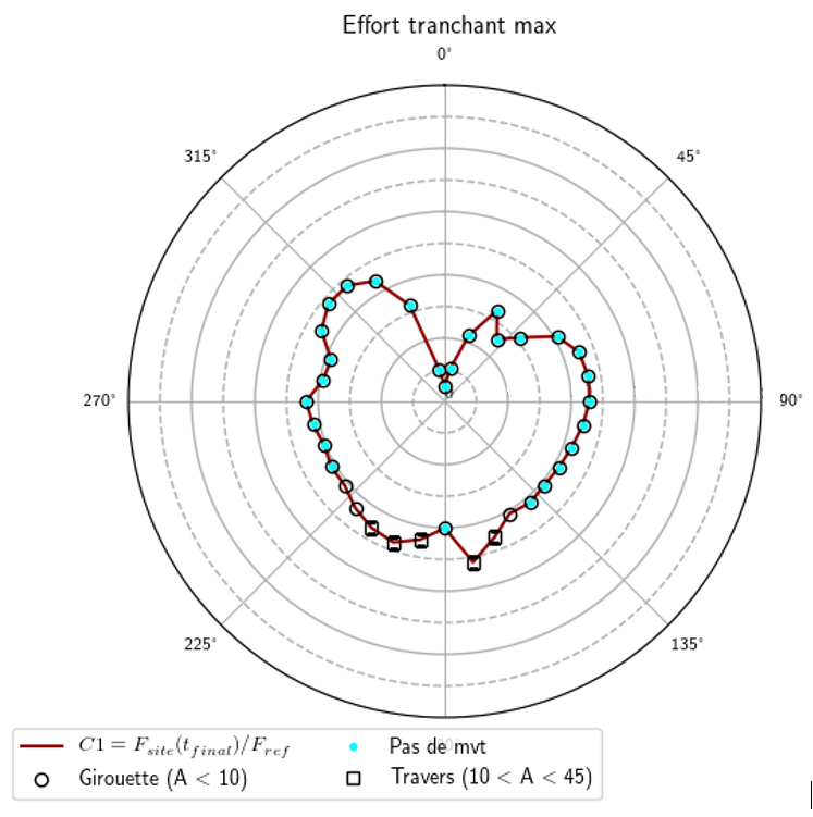
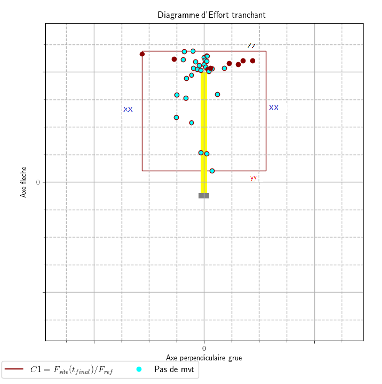
  • 4th step: risk assessment: self-rotation, misalignment, maximum lateral force, etc.
Carte de comportement de la grue sur le site pour l'ensemble des directions de vents et des positions de la crue Carte radar d'effort tranchant maximal pour les directions de vent Diagramme d'effort tranchant

How is the stability of cranes under site effects calculated?

Use cases

Case n°1 : one crane

  • Analysis with and without windbreak sail
  • No cases of self-rotation detected
  • Adjustment of jib height/crane position according to project phasing

Cas n°2 : Two cranes

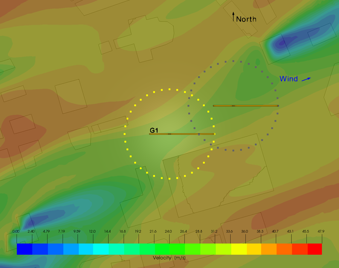
  • Simultaneous analysis of two cranes at different heights
  • Identification of areas with high wind speed gradients
  • Differentiated recommendations according to crane position
Exemple de résultats : champ de vitesse de vent pour une direction donnée avec positions étudiées des grues, pour un cas avec 2 grues Exemple de résultats : champ de vitesse de vent pour une direction donnée avec positions étudiées des grues

Results delivered

  • Reduced risk of critical or unstable jib orientation;
  • Safer design of construction site installations.

Benefits of the method

  • Precise detection of critical or dangerous positions;
  • Internal tool adaptable to all types of cranes;
  • Support for decision-making regarding site layout and safety.
  • Tool adaptable to any urban site with complex geometry.

Required input data

  • Crane installation plan on the construction site;
  • Shape and height of buildings within a 1 km radius of the crane;
  • Crane characteristics (drag coefficients*, moment of inertia, friction, brakes, etc.);


*If the drag coefficients are unknown, they can be determined by additional CFD simulations. This requires the plans or 3D model of the various components that make up the crane jib and counter jib.

Contact us

to find out more or request a demonstration!